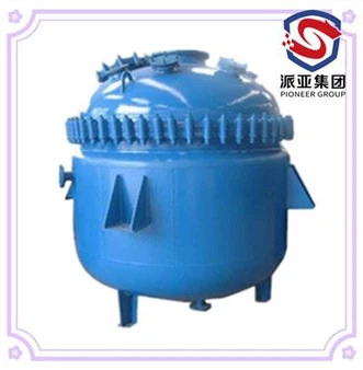

1. Preperation
1.1 Clean the glass/enamel surface of the glass lined reactor/GLR inner vessel with filtered clean water before installation.
1.2 Prepare installation and maintenance tools and parts: new agitators, 2/5T traveling cranes or manual hoists, soft rope ladders, flange clamp wrenches, bolt wrenches, top threaded lifting eye of agitator, soft felt or soft cloth, tape, butter or antirust lubricating oil, and other spare parts that need to be replaced;
1.3 Take off the pipeline which connected to the nozzles on the reactor top head and pipeline which connected to mechanical seal for empty the space for agitator
replacement; Set up the manual hoist bracket (if there is no crane or other lifting equipment on site);
1.4 Exposed glass lined nozzles shall be covered with soft cloth for protection;
1.5 Check the removed nozzle gaskets and replace it when re-installing if it loses elasticity;
1.6 Open the manhole of glass lined reactor/GLR, and worker should wear clean soft-soled rubber shoes to enter the vessel of GLR by a rope ladder.
1.7 Lay soft felt on the bottom of the reactor vessel to avoid glass attack by agitator or tools falling
1.8 Wrap soft felt or soft cloth on the agitator blade and fix it with tape to avoid glass attack of the vessel inner wall during agitator hoist out;
1.9 After upper work finished, the worker should move off from the vessle and take off the rope ladder.
2. Remove the motorgear device and motorgear frame
2.1 Unhook the motor connecting cable under power cut;
2.2 Loose the bolts of coupling,detach the agitator shaft and reducer shaft;
2.3 Before move away the reducerr, corresponding marks shall be made on the side both of the frame flange and reducer flange to prevent displacement during re-installation;
2.4 Loose the fixing bolts of reducer flange, remove the motorgear device and keep properly;
2.5 Install the top threaded lifting eye of agitator and lifting it tightly by crane or manual hoist;
2.6 Clean the agitator shaft and bearing house of frame, and then apply a small amount of grease (mechine butter) on the agitator shaft;
2.7 Loose the fixed ring of the sealing ring of the mechanical seal, move the sealing ring up to lower position of the frame bearing, and place a soft cloth above the mating ring to protect the end-face of mechanical seal;
2.8 Loose the shaft positioning screw ring and thrust washer on the top of frame bearing;
2.9 Slowly lower down the agitator to the bottom of the vessel by crane or a manual hoist (it can help to knock the top of the shaft head by hammer with a wooden pad to help the agitator to lower down);
2.10 Remove the top threaded lifting eye, shaft positioning screw ring and thrust washer;
2.11 Before move away the frame, corresponding marks shall be made on the side both of the frame flange and mounting flange to prevent displacement during re-installation;
2.12 Loose the fixing bolts of frame, vertical remove the frame slowly by crane or manual hoist and keep properly, pay attention to the shift key which lock on the bearing seat during lifting, and take it away in time to prevent it from falling;
2.13 Take away the sealing ring of the mechanical seal from the agitaor shaft and keep properly.
3. Lifring out the reactor top head and take out the damaged/old agitator;
3.1 Before move away the top head of reactor, corresponding marks shall be made on the side both of the top head flange and vessel flange to prevent displacement during re-installation;
3.2 loose the bolts of mating ring cover to avoid matong ring broken by collision durng move away the top head, if necessary, the whole mechanical seal water jacket can be disassembled and taken out to expose the nozzle (soft cloth is required set betwenn aigitaor shafe and nozzle for protection);
3.3 Loosen and remove the clamps diagonally which connected the reactor top head to vessel and keep properly;
3.4 Slowly lifting up and remove the top head by a crane or a manual hoist connected the lifting eye which on the reactor top head, pay attention to straighten the agitator shaft by a worker during lifting to avoid knock the mating ring of mechanical seal and inner vessel, then put the top head to a free ground which covered with felt or soft cloth;
3.5 Install the top threaded lifting eye of agitator and lifting out the damnaged agitaor by crane or manual hoist or manual.
4. Lifting in the new agitator
4.1 Unpack the upper shaft of the new agitatort, check whether the accessories are complete (connecting key, positioning nut ring and thrust washer), and remove the above accessories from the new agitator shaft;
4.2 Install the top threaded lifting eye on the new agitator shaft end and lifting in the new agitator to the vessel by a crane or manual hoist, placing the bottom center of the agitator shall be aligned with the discharge nozzle;
4.3 Remove the top threaded lifting eye and place agitator properly.
5. Assembly the reactor top head
5.1 Clean the flange end both vessel and top cover, check and place the gasket(suggest change a new one);
5.2 Hoist the top head, put the agitator vertically, align the agitator shaft top with the agitaor nozzel of the top head, carefully lower down the top head vertically and gently, and insert the agitator shaft into the the agitaor nozzel of the top head and the mechanical seal water jacket until the top head flange falls to the vessel flange and aligned;
5.3 Slightly lift up the top head and adjust the position of the top head according to the corresponding marked position and then faling down the top head;
5.4 Tighten the clamps diagonally which connected the reactor top head to vessel , pay attention to the number and tighten torque of clamps, and replace it if damaged;
5.5 Open the manhole of glass lined reactor/GLR, and worker should wear clean soft-soled rubber shoes to enter the vessel of GLR by a rope ladder to clean up all the new agitator packages and others.
6. Install meichanical seal and motorgear frame
6.1 Apply a small amount of grease (mechine butter) on the inner surface of sealing ring assembly, and then put it into agitator shaft carefully;
6.2 Tighten the head cap screw of the sealing ring and fix it on the position of agitator shaft near the mating ring;
6.3 Put the cover of sealing oil tray into agitator shaft;
6.4 Clean the connected flange face for frame installation;
6.5 Hoist the gearmotor frame, put the end of agitator shaft into the frame bearing carefully, and then fix the frame to the mounting flange with bolts corresponding to the holes according the marked position. ( Be careful to prevent bumps. Pay attention to the corresponding positions of the keyway from bearing to the agitator shaft. Pay attention to the position of the opening in the bottom of the frame to avoid blocking the cooling water connection of seal box.)
6.6 Adjust the verticality and levelness of frame, and then tighten fastening bolts diagonally;
Put the thrust washer and positioning screw ring into the agitator shaft;
6.7 Install the top threaded lifting eye on the new agitator shaft top-end, and then lifting up the agitator shaft slowly by a crane or manual hoist, install the key when the corresponding positions of the keyway from bearing to the agitator shaft, lock the positioning screw ring tightly to fix the agitator shaft on the bearing after agitatot shaft posited;
6.8 Remove the protective material between the sealing ring and mating ring, loose the bolts of mating ring cover, then adjust the clearance between the shaft surface and mating ring, then tighten fastening bolts of mating ring cover diagonally and appropriately (Since themating ring is generally made by hard material, such as ceramics, and it is easy to break; so the tightening strength must be controlled within a reasonable range. During the process, pay attention to the clearance between the mating ring and the shaft, and tighten it diagonally);
6.9 loose the head cap screw of the sealing ringassembly, press the end-face of sealing ring to contact the end-face of mating ring, and then press the sealing ring spring to a certain amount of compression (2 ~ 3mm), lock the head cap screw of sealing ring assembly for positioning;
6.10 After positioning of sealing ring assembly, install the half-ring on the top of sealing ring assembly closely and tight the head cap screw of half-ring for positioning ( Try to make the clearance as smooth as possible; and the half-ring incision should stagger the position of the sealing ring assembly with small spring);
6.11 Loose the head cap screw both side of the sealing ring assembly at same time, and then djust the compression of the mechanical seal through the top bolts on the half ring.
7. Install driving device and coupling
7.1 Clean the connected flange face of frame and reducer;
7.2 Hoist the motorgear device to the frame top flange, and then fix the recucer flange to the frame flange with bolts corresponding to the holes according to the marked position .
7.3 Adjust the position of reducer shaft head keyway to correspond to the agitator shaft head keyway, install the semicircular coupling after installing the key.
8. Pipeline connection and motor wiring
8.1 Connect the pipeline to sealing box of mechanical seal according to the marks on the sealing box body;)
8.2 Fill sealing liquid to the sealing liquid tray till the level 15-20mm above the end-face. (Sealing liquid: Clean glycerin, engine oil, pure water, etc.)
8.3 Connect the pipeline to the top head nozzles
8.4 Wiring the motor with cables.
9. Inspection After Installation
9.1 Voltage and electric control system connection.
9.2 Each sealing of the inlet and outlet connections of different fluids.
9.3 The sealing & connection by the head/cover and vessel body.
9.4 The sealing & connection of mechanical seal, the level of sealing liquid of mechanical seal.
9.5 The sealing & connection pipe of the pressure relief system.
9.6 The sealing & connection of heating/cooling pipeline.
9.7 The oil level of the gear reducer,lubrication oil of bearing house.
9.8 The equipment, electric control and instruments should all meet the factory explosion-proof requirements. Safety valves, thermometers and pressure gauges all need to be calibrated, and then can be use after inspections are passed.
9.9 After glass lined equipment is installed, it should be carefully inspected with the vessel and each parts, confirm there are no missing items and tools, and then do the running test with water.
10. No-load test and running test with water of glass lined reactor (please refer the operation manuel of glass lined reactor )
11. Running test of mechanical seal (please refer the operation manuel of mechanical seal)